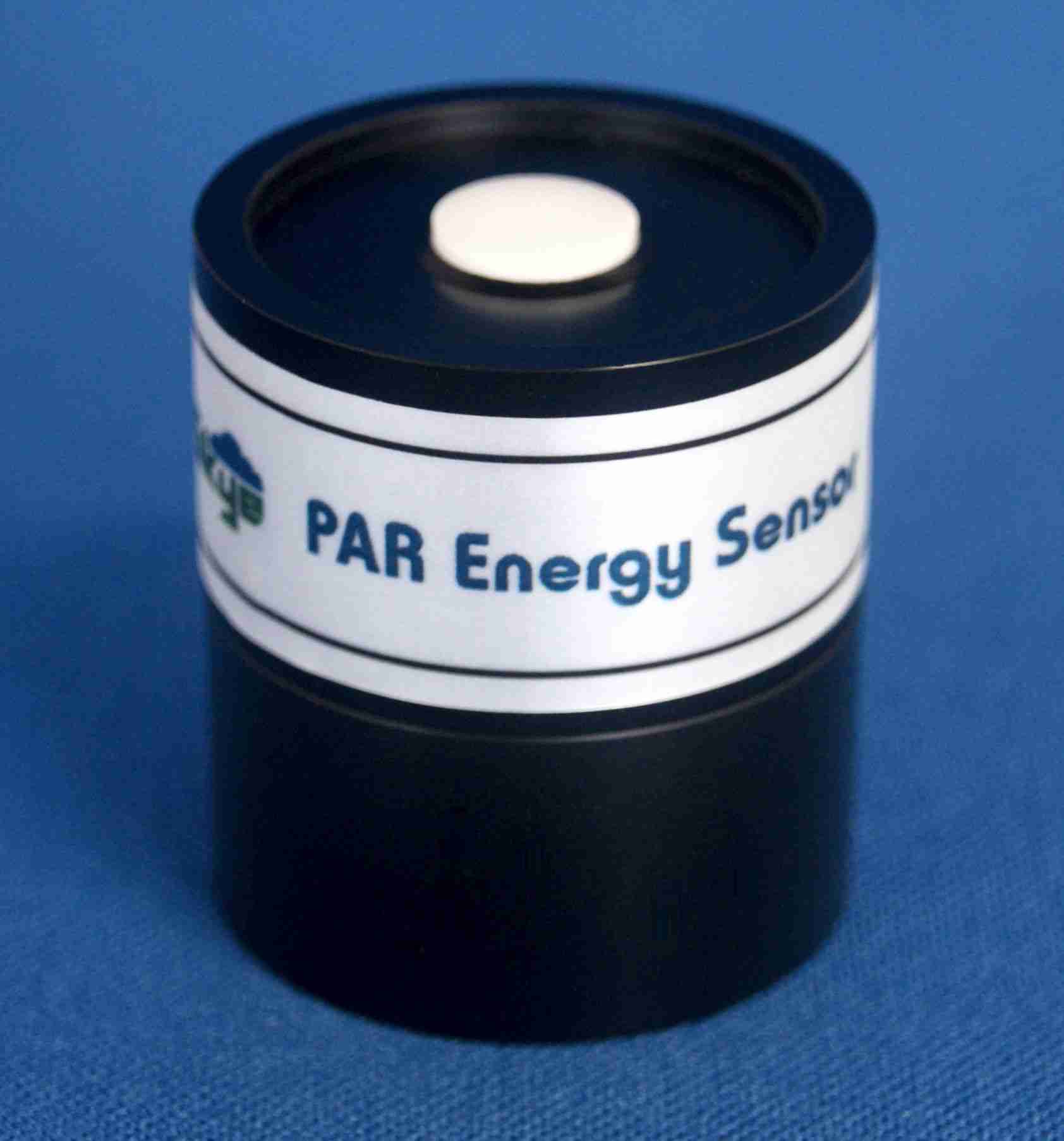
CALIBRATION PROCEDURE
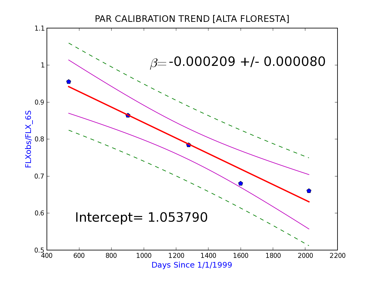
When possible, calibration of the PAR sensors was accomplished by using in-situ comparisons to a radiative transfer model calculations of flux on selected optimal days. The 6S [Vermote et al, 1997] model we used for this purpose is based on the successive order of scattering method. Field days used were of minimal aerosol-loading (AOT500nm < 0.1) under cloud-free conditions. Such aerosol levels are sufficiently low to render an exact knowledge of the absorption properties unimportant for computing clear-sky insolation to an accuracy of >1%. The manufacturer (Skye Instruments) states an initial accuracy for its factory calibration of 5% (generally < 3%). However, due to changes in the stability of the silicon detector (estimated by Skye as ~ 2% per year) and more notably, diminished transmittance of the bandpass interference filter upon prolonged exposure, we observed significant degradation of sensitivity in these sensors of approximately 6-8% per year. This necessitated that we employ in-situ calibrations when possible to ensure the best possible determination of PAR calibration. The utility of this technique varied greatly depending on local climatology (a cloudless sky with low AOT is required) and thus our estimation of PAR flux accuracy varies with site. At some locations, such as Alta Floresta, Brazil, we benefited from an environment that presented numerous optimal calibrations dates and were able to characterize the trend in calibration drift with high confidence [In-situ calibration plot]. Locations with few, or no suitable calibration conditions (such as persistently cloudy locations) are necessarily calibrated with the manufacturer's calibration only, and thus are not considered suitable for promotion to the highest quality level (2.0). More on data quality designations can be found in the Data Quality Assessment section below.
Due to additional complicating factors, such as water vapor influence, thermal equilibrium issues, and also, because of the greater degree of accuracy (2%) provided by the manufacturer and generally much greater stability of this type of radiometer, the factory calibrations were used for the pyranometers. These pyranometers have all been observed to retain consistent calibration coefficients (calibration drift less than 1% per year) between re-calibration sessions.
PROCESSING
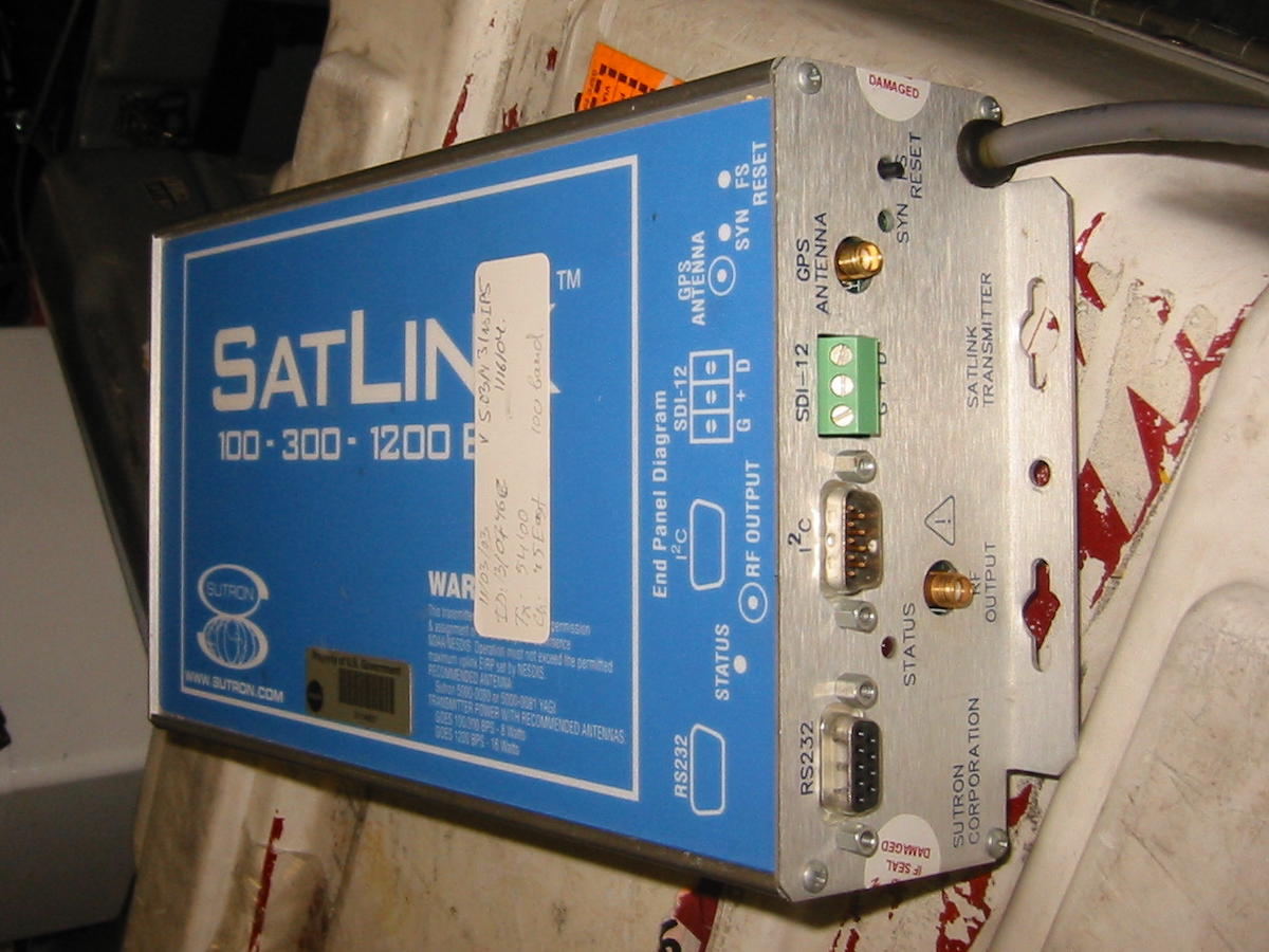
Data from all AERONET sites are sent hourly from each fieldsite to the Wallops Receiving Center via transmissions to satellite (GOES, METEOSAT) using VITEL transmitters. These raw data are then transferred hourly from the Wallops receiving station to the Goddard Facility.
The instrument-specific calibrations are applied and the raw data are converted to flux data products that are made available on the website. |
